Thermostat Wiring Diagram For Electric Furnace
This is the most common configuration f. 1 3 4 2 photograph your wiring this is important.
Lennox Thermostat Wiring Diagram Most Lennox Furnace Thermostat Wiring Diagram Best Of With

1 trick that we 2 to printing a similar wiring plan off twice.

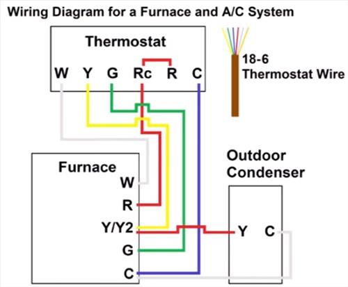
Thermostat wiring diagram for electric furnace. The most basic thermostat has 2 wires; Janitrol furnace thermostat wiring diagram from i.ytimg.com. Air handler, ac separated from furnace, rc and r jumper removed.
This diagram is to be used as reference for the low voltage control wiring of your heating and ac system. Therefore, you will use the following color code for simple thermostat wiring: Thermostat in conjunction with the furnace wiring diagram.
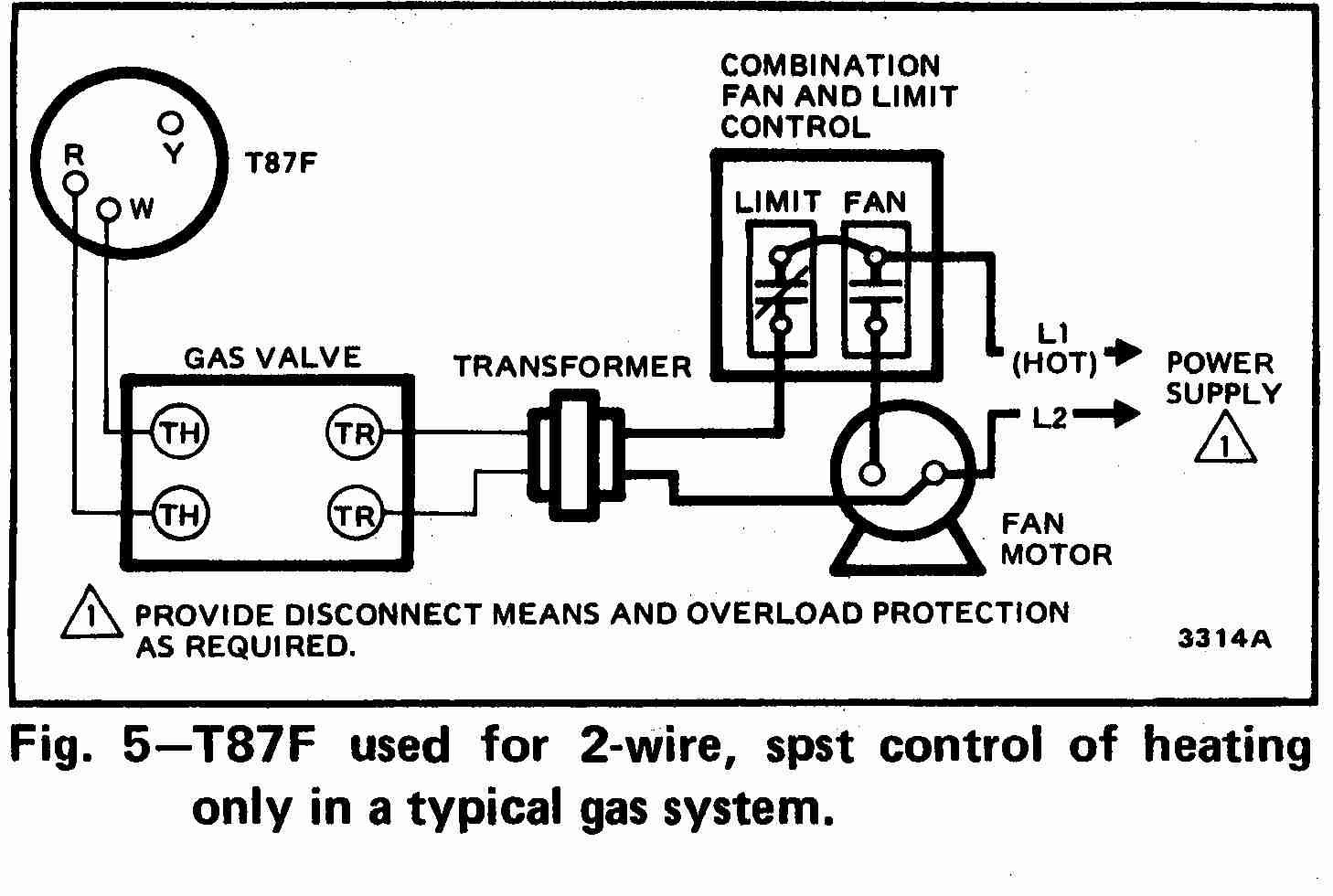
Occasionally, the cables will cross. Refer to unit wiring diagram section for wiring of sequencer for each model furnace. L only connected if heat pump has a fault terminal.
Print the wiring diagram off plus use highlighters to trace the signal. 11 goodman furnace thermostat wiring diagram. **refer to the blower chart for cfm requirements.
A wiring diagram is a streamlined standard pictorial depiction of an electric circuit. Air handler, heat pump, electric resistance. The wire schematic for the unit should be right on one of the doors top or on the blower door.
Air handler, ac, and boiler, rc and r jumper removed. But, it does not mean connection between the cables. The line voltage feeding the furnace to operate the fan blower motor is transformed down to a safer level of 24 volts the gas control valve needs 24 volts to open and after making a series loop.
The thermostat uses 1 wire to control each of your hvac system’s primary functions, such as heating, cooling, fan, etc. Installation leads to a hazardous electrical condition and to premature furnace failure, thus. The most important is furnace stages motor speeds and fuel type.
Red wire for power (24h). Wiring a 2 wire thermostat is pretty straightforward. Always refer to your thermostat or equipment installation guides to verify proper wiring.
Basic thermostat wiring for furnace and air conditioner. Nordyne air handler wiring diagram fan circuit free for ac model e2eb 015ha 2 with e2eb 015ha wiring diagram electric furnace thermostat wiring carrier furnace pin on a7x new wiring diagram. A wiring diagram is a simplified standard pictorial representation of an electric circuit.
Thermostat wiring explained regarding furnace thermostat wiring diagram image size 592 x 667 px. According to earlier the lines in a 2 wire thermostat wiring diagram heat only represents wires. These run from the thermostat to the furnace and control the.
This can be useful for both the individuals and for specialists who’re looking to find out more on. That’s why we only need two wires: Electric furnace thermostat wiring diagram from i.pinimg.com.
As shown in the wiring diagram for your unit, the blower speed is determined. 4 wire honeywell thermostat rth111b wiring diagram wiring diagram is a simplified normal pictorial representation of an electrical circuit. If you need manuals wiring and parts diagrams for your coleman or nordyne furnace we have partnered with aberdeen home repair to help you find them.
Element rating labels and furnace wiring diagrams. When you make use of your finger or perhaps the actual circuit with your eyes, it is easy to mistrace the circuit. Janitrol furnace thermostat wiring diagram.
You’ll be in a position to understand specifically when the assignments should be finished, that makes it much simpler for you to. Variety of wiring diagram for mobile home. 1 stage hp 95% & 80% single stage x13 gas furnace hw vp 9000 wd18 2 stage hp 95% & 80%single stage x13 gas furnace hw vp 8000:
1 heat / 1 cool thermostat. Heating only thermostat wiring diagrams if you only have a furnace such as a gas furnace, oil furnace, electric furnace, or a boiler. Basic gas furnace wiring diagram wiring diagram is a simplified conventional pictorial representation of an electrical circuit it shows the components of the circuit as simplified shapes and the capacity and signal associates amongst the devices.
Usually a red and a white wire. Print the wiring diagram off plus use highlighters to trace the signal. Description, coleman mobile home electric furnace wiring diagram coleman in coleman mobile home furnace wiring diagram, image size 400 x 300 px, and to view image.
Used on modulating furnaces when there is a single stage thermostat for cooling. Terminal r or terminal rh for the red wire. 1 trick that we 2 to printing a similar wiring plan off twice.
Gas furnace thermostat wiring diagram. Two wire thermostat wiring is used for furnaces only and usually doesn’t need a “c” or “common” wire. In addition, wiring diagram provides you with the time body during which the projects are for being completed.
R = power rh= heat transformer power rc= cooling transformer power w =heatimg load y = compressor g =fan if this is just heat you only need the r and w ed upvote thread tools search this thread show printable version email this page There will be main lines that are represented by l1, l2, l3, and so on. Jump if needed to achieve correct cfm.
This originates from the transformer. Note y2 some ac systems will have a blue wire with a pink stripe in place of the yellow or y wire. Electric furnace thermostat wiring diagram.
The function of the transformer is to supply the 24 The advantage of a two stage furnace is that it extends the run time which does a better job distributing the air in your home. Qest angle stop valve 1/2 x 1/2 for mobile homes.
When you make use of your finger or perhaps the actual circuit with your eyes, it is easy to mistrace the circuit. If not the structure wont function as it should be. (ruud and rheem, reversing valve powered in heating mode) 1 heat / 1 cool thermostat.
See the diagram below for what each wire controls on your system: The most basic of systems (such as an older ‘heat only’ forced air / gas furnace with a standing pilot light) only need two wires for control. According to previous, the lines in a trane thermostat wiring diagram represents wires.
Injunction of 2 wires is generally indicated by black dot on the junction of 2 lines. 2.nortron by broan electric furnaces heating pcbelement sequencing amps motor type motor hp cfm (heating mode. Control transformer (figure 3) all e2 furnaces are equipped with a 30 va, 240/208 vac primary, 24 vac secondary transformer.
I show where the wires go at the thermostat, the color code, then down at the furnace control board,.
Find Out Here Intertherm thermostat Wiring Diagram Download

Thermostat Wiring to a Furnace and AC Unit! Color Code, How it Works, Diagram! YouTube in 2020

Famous Lennox Thermostat Wiring Diagram Image Collection Best At Furnace Thermostat wiring

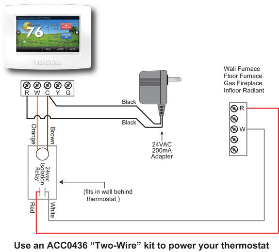
Thermostat for Wall or Floor Furnace HVAC PROBLEM SOLVER
Intertherm Electric Furnace Wiring Diagram Download

Intertherm thermostat Wiring Diagram Download

hvac Connecting Wood/Electric Furnace to Smart Thermostat Home Improvement Stack Exchange

Guide to wiring connections for room thermostats
RV FURNACE THERMOSTAT WIRING Auto Electrical Wiring Diagram

I'm trying to connect a Nest thermostat to my Lennox electric furnace/ac. But it's coming up

electrical Add c wire to furnace for smart thermostat Home Improvement Stack Exchange

Wiring Diagram for thermostat to Furnace Collection

Find Out Here Intertherm thermostat Wiring Diagram Download

Wiring A Furnace Thermostat Diagram Database Wiring Diagram Sample

Columbia Furnace and Honeywell Thermostat Wiring Community Forums

Goodman Furnace Thermostat Wiring
Intertherm thermostat Wiring Diagram Download

Thermostat Wiring Explained

Furnace Thermostat Wiring and Troubleshooting HVAC How To