Dexter Electric Brakes Wiring Diagram
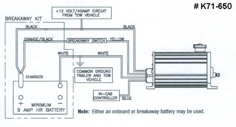
If you are referring to two white wires from the brake magnet that are coming from the rear of each electric brake assembly, then it would not matter which wire is connected to ground and which wire is used for the brake feed. Under no circumstances should the actuator blue wire and the yellow wire be connected together, nor should the blue wire ever be grounded.
Dexter Trailer Brakes Wiring Diagram Wiring Diagram
This controller features a patented accelerometer design which senses the deceleration of the towing vehicle and sends a proportional voltage to the electric trailer brakes.

Dexter electric brakes wiring diagram. Even the slightest imbalance of the trailer brakes might cause the rider to lose control. Wiring diagram for utility trailer with electric brakes. Under no circumstances should the blue wire and the yellow wire be connected together, nor should the blue wire ever be grounded.
Dexter trailer brakes wiring diagram wiring diagram is a simplified good enough pictorial representation of an electrical circuit it shows the components of the circuit as. Connector used to connect and disconnect trailer and tow vehicle. See also solar panel wiring diagram schematic download.
Refer to the literature provided with the brake controller for greater detail in installing the controller. 12 awg 4 under 30 12 no. Dexter electric brakes wired in parallel.
Use this 4 pin trailer wiring diagram to properly wire your 4 wire trailer plug. We do have a wiring diagram for you! Blue electric brakes or hydraulic reverse disable see blue wire notes below in the trailer wiring diagram and connector application chart below use the first 5 pins and ignore the rest.
Breakaway switch switches battery power to brakes if Dexter electric brakes wired in parallel. The dexter wires are a connected pair of 20 awg wires, running through the hollow axle tubes.
Wiring diagram is a technique of describing the configuration of electrical equipment installation, eg electrical installation equipment in the substation on cb, from panel to box cb that covers telecontrol & telesignaling aspect, telemetering, all aspects that require wiring diagram, used to locate interference, new auxillary, etc.dexter electric brakes wiring diagram. I do not know what size main wire runs inside the hull, but in the left wheel well there are two pairs of 18 awg wires, one for each axle. Proper control of the brakes on these vehicles can be very difficult.
Dexter trailer brakes wiring diagram wiring diagram is a simplified good enough pictorial representation of an electrical circuit it shows the components of the circuit as simplified shapes and the capability and signal connections amongst the devices. (always ground trailer brakes through connector). The magnet that operates the electric brakes does not require the wires to be specific.
The white wire is the supply wire, the black wire is the dexter wire that crosses over to the right side brake: Controller electric brake controller provides power to the magnets to actuate the trailer brakes. Buydirect is the newest place to search.
Just let me know if you have any additional questions regarding the installation. Breakaway switch switches battery power to brakes if The yellow wire from the actuator is connected to the cold side of the trailer emergency breakaway switch.
Vehicle to be moving in order for the dexter e/h brake. The yellow wire from the actuator is connected to the cold side of the trailer emergency breakaway switch. Electric trailer brake wiring schematic.
For electric brake trailers, eager beaver can supply a proper truck harness and a brake controller. 10 awg 6 under 30 18 no. Use a 4mm x 2 core cable for your active and earth wires to the brakes separate from wiring used for lighting etc.
(always ground trailer brakes through connector). Connector used to connect and disconnect trailer and tow vehicle. 12 awg 2 6 no.
I have attached a wiring diagram and review videos for you to check out. Controller electric brake controller provides power to the magnets to actuate the trailer brakes. This automobile is designed not just to travel one location to another but also.
Dexter electric brakes wiring diagram. Titan brakes & actuators by dexter & ufp by dexter 1041 baxter lane, winchester, tn 37398, usa. A secondary issue is the spontaneous and unexpected actuation of the brakes.
Dexter axle does not recommend the use of brakes on small touring trailers designed to be pulled by motorcycles. Truck wiring see the trailer service manual for a schematic that shows how to properly wire the tow vehicle.
Dexter Trailer Brakes Wiring Diagram Wiring Diagram
Dexter Trailer Brakes Wiring Diagram Wiring Diagram
46 Dexter Trailer Brake Wiring Diagram Wiring Diagram Source Online
Dexter Trailer Brakes Wiring Diagram Trailer Wiring Diagram
46 Dexter Trailer Brake Wiring Diagram Wiring Diagram Source Online
Can Dexter Breakaway Kit for Electric Over Hydraulic Actuators be Used with Regular Electric Brakes
Wiring the Breakaway Switch to Dexter Electric Over Hydraulic Drum Trailer Brake Actuator
Dexter Trailer Brakes Wiring Diagram Trailer Wiring Diagram
Dexter Trailer Brakes Wiring Diagram Wiring Diagram
Dexter Trailer Brakes Wiring Diagram Trailer Wiring Diagram
Dexter Electric Brakes Wiring Diagram easywiring
Dexter Trailer Brakes Wiring Diagram Trailer Wiring Diagram
Dexter Electric Over Hydraulic Brake Actuator 1,600 psi Dexter Trailer Brakes K71651
Dexter Trailer Brakes Wiring Diagram Wiring Diagram
Dexter® Electric Trailer Brakes Right (Curb Side)
Dexter Hydraulic Brake Actuator Wiring Diagram
Dexter Trailer Brakes Wiring Diagram Trailer Wiring Diagram