Circuit And Wiring Diagrams
A wiring diagram is a simple visual representation of the physical connections and physical layout of an electrical system or circuit. Circuit diagram is a free application for making electronic circuit diagrams and exporting them as images.
Circuit Wiring Diagram
Start with a collection of electrical symbols appropriate for your diagram.

Circuit and wiring diagrams. A wiring diagram usually gives more information about the The usage of wiring diagram Introduction residual current circuit breaker elcb the fault current overloads and short circuits can be detected by circuit breakers like mcb s rcd type f residual current protection for single phase inverters applications type f.
It shows how the electrical wires are interconnected and can also show where fixtures and components may be connected to the system. These diagrams are an effective way of showing how wires are interconnected with different components in a system. It shows the components of the circuit as simplified shapes, and the power and signal connections between the devices.
A drawing meant to depict the physical arrangement of the wires and the components they connect is called artwork or layout, physical design, or wiring diagram. Circuit diagrams are used for the design (circuit design), construction (such as pcb layout), and maintenance of electrical and electronic equipment. Premium color wiring diagrams get premium wiring diagrams that are available for your vehicle that are accessible online right now, purchase full set of complete wiring diagrams so you can have full online access to everything you need including premium wiring diagrams, fuse and component locations, repair information, factory recall information and even tsb's (technical.
Circuit or schematic diagrams consist of symbols representing physical components and lines representing wires or. A simplified conventional pictorial representation of an electrical circuit. It shows the components of the circuit as simplified shapes, and how to make the connections between the devices.
Hager rccb wiring diagram wiring diagram is a simplified enjoyable pictorial representation of an electrical circuit. A schematic can contain few or many symbols and connections and is normally read from left to right, top to bottom. It shows how the electrical wires are interconnected and can also show where fixtures and components may be connected to the system.
A wiring diagram is a simplified traditional photographic representation of an electric circuit. Use line hops if any lines need to cross. When troubleshooting or designing control circuits , we use “ladder” or “schematic” diagrams to represent how the circuit works but these diagrams do not show how equipment is physically laid out, nor do they represent how things are wired “in the real world.”
Add layers to show complexity. A wiring diagram is simply a pictorial representation of all the electrical connections in a specific circuit. A wiring diagram is a pictorial representation of an electric circuit, where the elements of the loop and the signal connections between devices and the power source are shown in the conventional methods as simplified shapes.
Circuit diagrams are widely used for circuit design, construction, and maintenance of electrical and electronic equipment. The schematic diagram of an electrical circuit shows the complete electrical connections. Household electric circuits the complete guide to electrical wiring control circuit diagram ring and radial multiwire branch 101 tracing 3 wire jlc online short types everything you need panel of diy home simulation 31 common wirings system electrical4u mz global sensor load light switch diagrams do it in.
A wiring diagram is a simple visual representation of the physical connections and physical layout of an electrical system or circuit. Delco circuit and wiring diagrams automobile systems to the close of the 1915 season index _____ page no. What does a wiring diagram look like?
Wiring diagrams can be helpful in many ways, including illustrated wire colors, showing where different elements of your project go using electrical symbols, and showing what wire goes where. A block diagram is a type of electrical drawing that represents the principle components of a complex. This size breaker requires a minimum of a #10 gauge wire so this wire used would be a 10/2 with ground.
A wiring diagram is a simplified conventional pictorial representation of an electrical circuit. Different types of electrical diagrams and drawing block diagram. A circuit diagram (also named electrical diagram, elementary diagram, and electronic schematic) is a graphical representation of an electrical circuit.
A diagram that represents the elements of a system using abstract, graphic drawings or realistic pictures. The 3 prong dryer wiring diagram here shows the proper connections for both ends of the circuit. Drag and drop symbols to the circuits and connect them.
Using some equations like v=ir or p=iv will allow you to calculate impedance, current, power and voltage in each part of the circuit. A pictorial circuit diagram uses simple images of components, while a schematic diagram shows the components and interconnections of the circuit using standardized symbolic representations. Draw circuits represented by lines.
Wiring diagrams for multiple receptacle outlets do it yourself help com. This is why a good diagram is important for wiring your home accurately and according to electrical codes. A house wiring diagram is thus, a wiring diagram of a house.
Ladder diagrams show how a circuit works logically and electrically. Figure 4—schematic diagram wiring diagram (or pictorial): A circuit diagram (wiring diagram, electrical diagram, elementary diagram, electronic schematic) is a graphical representation of an electrical circuit.
A wiring diagram is a simplified conventional. Duplex, gfci, 15, 20, 30, and 50amp receptacles. A drawing of an electrical or electronic circuit is known as a circuit diagram, but can also be called a schematic diagram, or just schematic.
A wiring diagram is a simplified conventional pictorial representation of an electrical circuit. The presentation of the interconnections. A wiring diagram is a simplified conventional pictorial representation of an electrical circuit.
The wiring diagram shows different components in a circuit via different shapes and symbols. Making wiring or electrical diagrams is easy with the proper templates and symbols: All the light wiring diagrams are available in the old and the new cable colours to avoid confusion.
A wiring diagram usually gives information about the relative position and arrangement of devices and terminals on the devices, to help in building or servicing the device.
Motor Forward Reverse Wiring Diagram Elec Eng World Electrical circuit diagram, Basic

Retro PWM Wiring Diagram

House wiring, Electrical wiring diagram, Diagram

Wiring Diagram Circuits Circuit Diagram
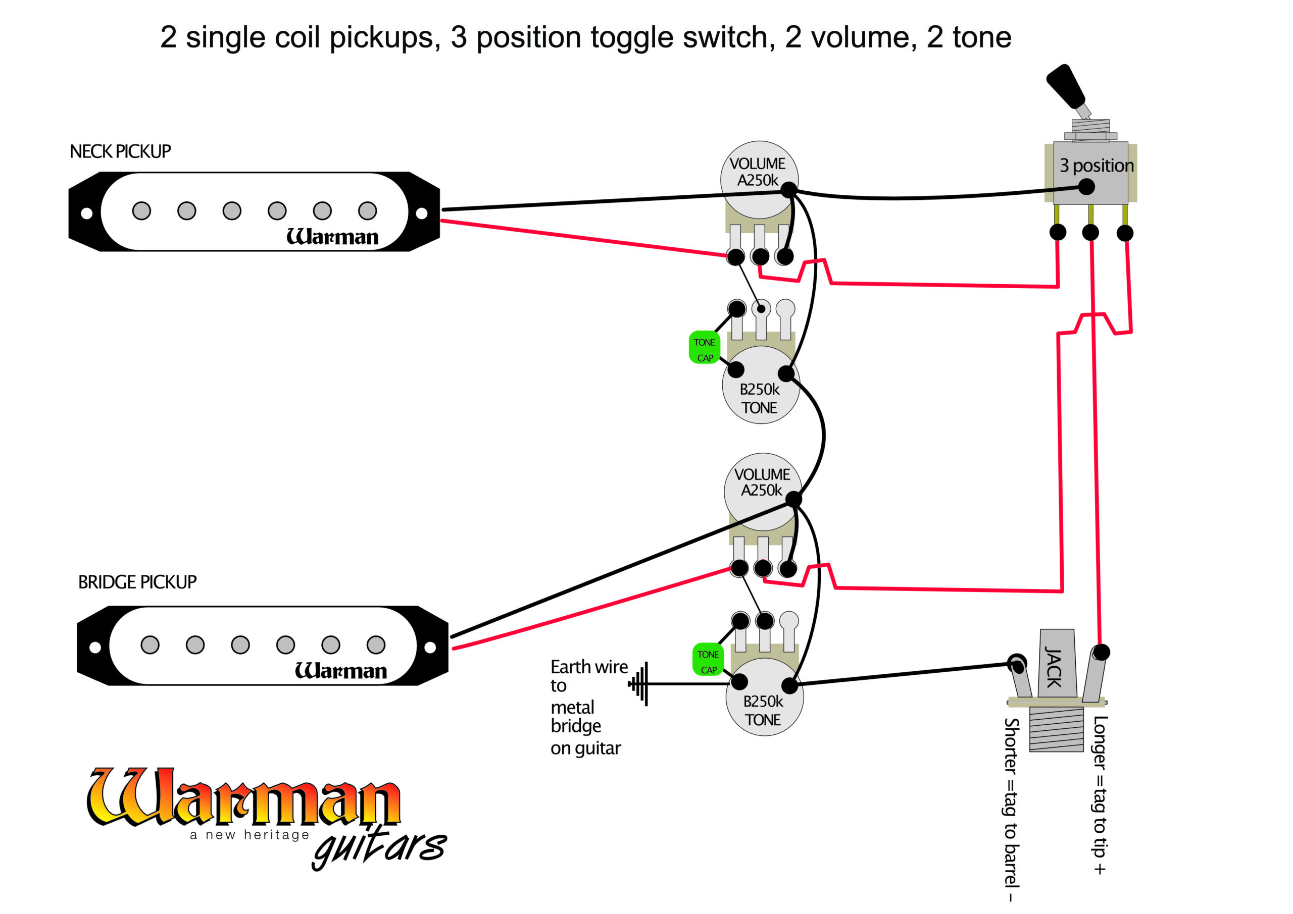
Basic guitar circuit wiring Part 2 Warman Guitars
Irrigation Pump Start Relay Wiring Diagram Collection

220 Breaker Box Wiring Diagram Collection

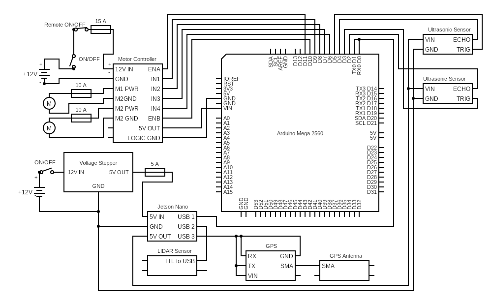
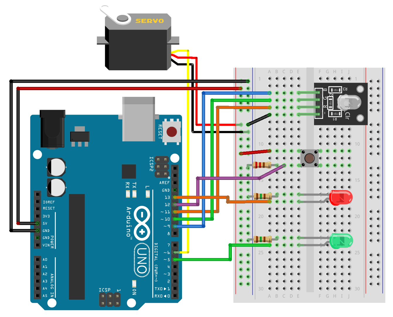
Fritzing Circuit & Wiring Diagrams
Two Wire & Three Wire Motor Control Circuit Motor Control Circuit Diagram Electrical A2Z
Electrical Engineering World GROUND FAULT CIRCUIT INTERRUPTER (gfci) Outlet Wiring Diagram
%2BOutlet%2BWiring%2BDiagram.jpg)
Circuit diagram WALLE

Electrical Engineering World Circuit Breaker Wiring Diagram

Three Phase Motor Control Circuit Diagram Pdf
What are the Ring Circuit and Radial Circuit? What Is Radial and Ring Circuit? Think a simple
Decoding wiring diagram in automobiles Launch Car Scanner
How to Wire Circuits from Schematics YouTube

Wiring Diagrams P90/Jazzmaster LAMBERTONES, LLC

wiring What's a schematic to other diagrams)? Electrical Engineering Stack Exchange

Wiring Diagram