Tachometer Circuit Diagram Using Arduino
With the advent of modern electronics, the tachometers have changed a lot. It is a home made reliable tachometer, that can be used with an arduino uno or nano that you can make to measure the speed of rotating objects on tools, bicycles, and robotics.
Michael McKGyver McKinley / Arduino_Tachometer

Working of the circuit is simple.
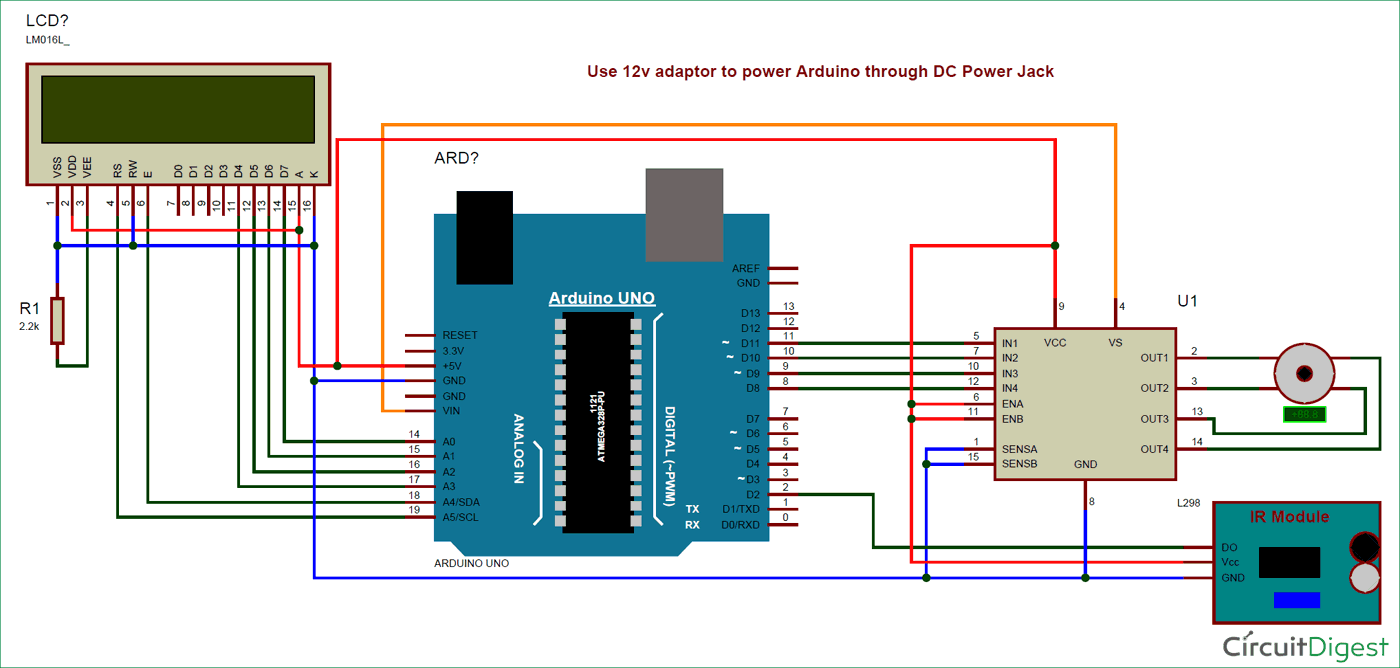
Tachometer circuit diagram using arduino. Place ir senor module on pcb in way that its sensor face toward the. Diy tachometer to measure accurate rpm using arduino. The circuit diagram of the digital tachometer using arduino is shown below.
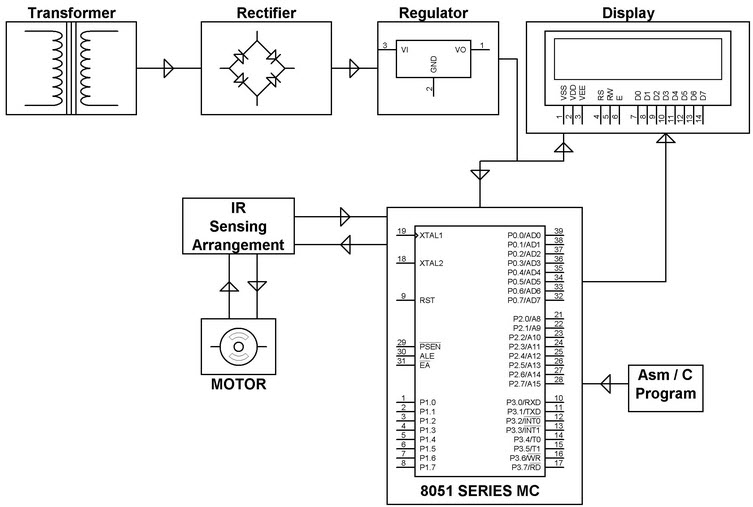
Some time we required to check the rpm of the motor while creating projects. After connecting all the components according to the circuit diagram, now time to turn on the circuit power supply using turn on the slide switch. Place ic2 such that when the motor shaft rotates, it cuts the ir signal to produce pulses at its output pin 3.
This circuit diagram (click on the link) should be sufficient to connect you ir module to your arduino. This is a digital tachometer using hall effect magnetic sensor, arduino nano and show the result on 4 digit 7 segment display. We have so many collections wire wiring diagrams and schematics, possibly including what is you need, such as a discussion of the circuit diagram of tachometer.
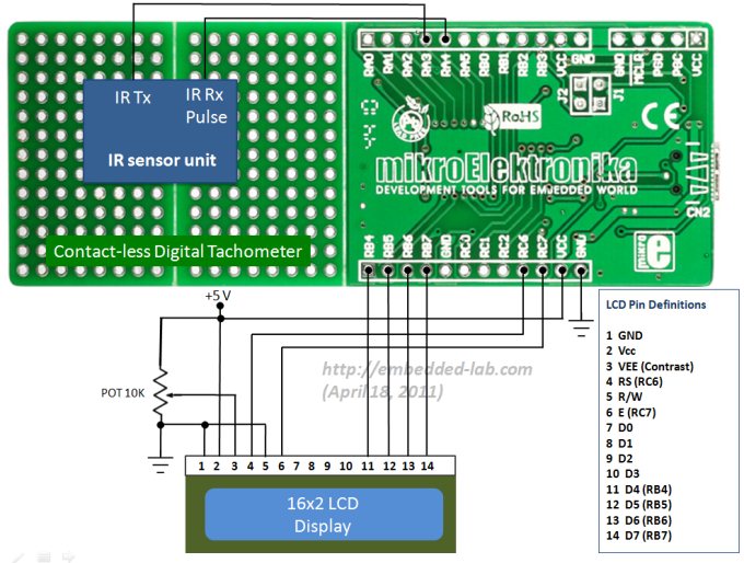
Then connect the 9v battery to power up arduino & lcd 16 x 2 screen Tachometer is a rpm counter which counts the no. The rpm and all the other information are displayed on a 16x2 lcd screen.
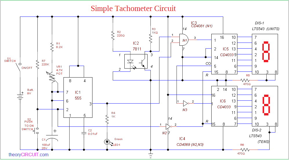
Make solder connection where it is required, refer electrical drawing for better understanding. // no of wings of rotating object, for disc object use 1 with white tape on. To identify the rotation speed or revolutions per second (rps) of rotating shaft or wheel we need tachometer, here simple tachometer circuit designed by using easily available elements slotted opto isolator module moc7811 and two seven segment display unit, by using this circuit we can measure spinning shaft or disc.
Here we are using the ir sensor module, which is works as an obstacle detector. Here is a simple circuit that can be used as a tachometer. The module itself will have 3 pins.
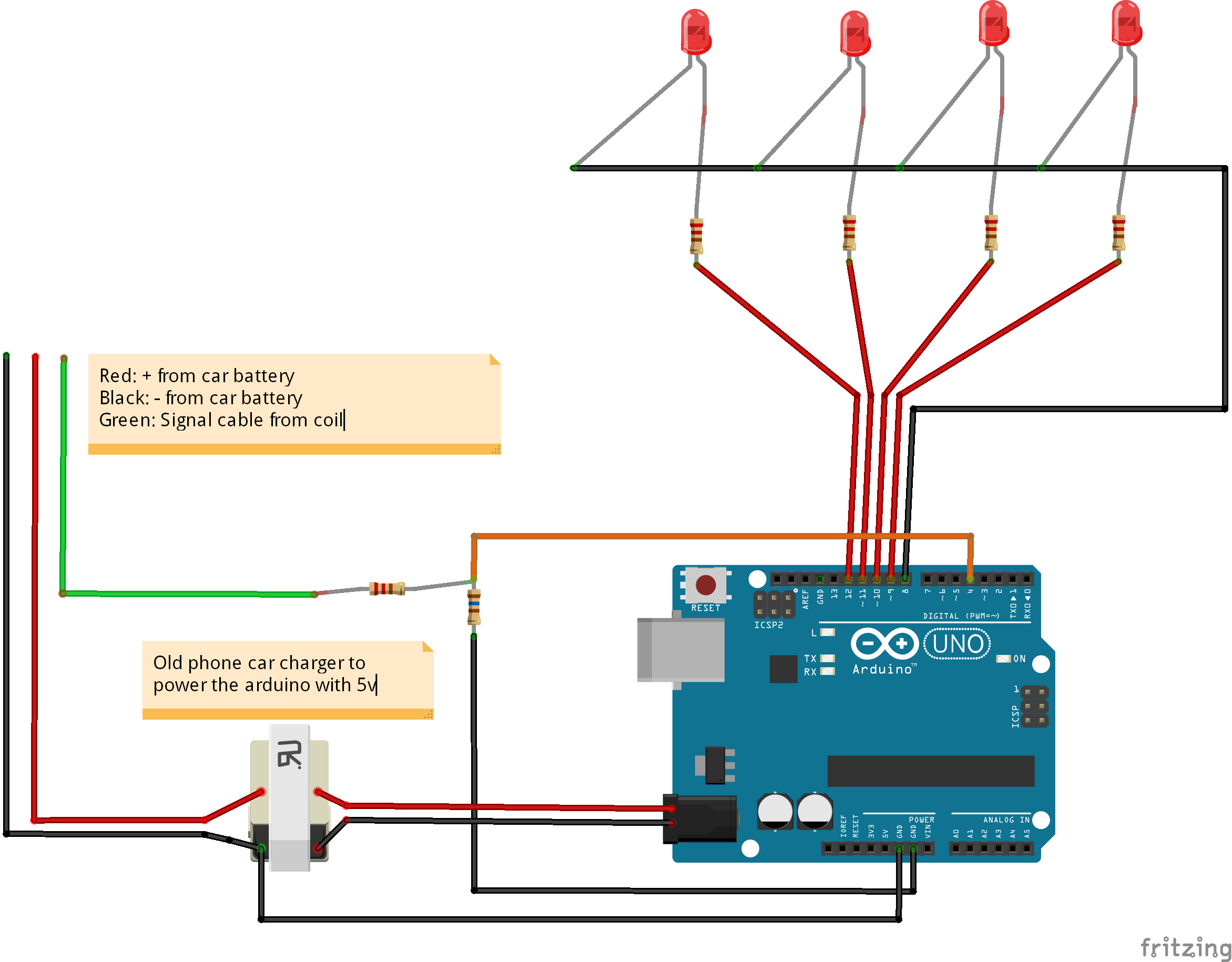
“tach” deals with more fundamental the rpm. Arduino tachometer circuit for precise readings. The resistor is used to prevent excess current which would normally damage the arduino.
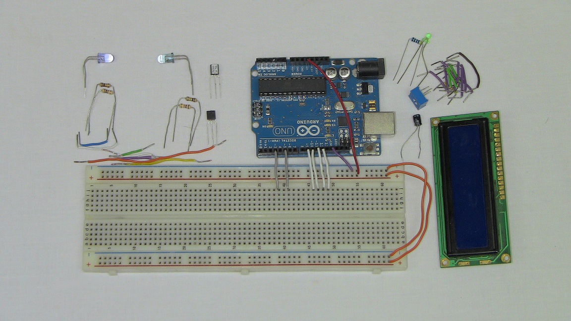
The circuit diagram is as shown in the circuit diagram tabs. Place arduino and lcd screen on pcb. Easy peasy reliable tachometer, that you can use to measure the rpm of tools, bicycle wheels, and robots using inexpensive parts.
For using this circuit as an automobile tachometer, the input terminal a. The arduino uno is a microcontroller board based on the atmega328. The deflection on the ammeter will be proportional to the frequency of the incoming signal.
In this method we are using arduino to build the tachometer by interfacing it with ir sensor to calculate the rpm to display the rpm on 16x2 lcd display module with i2c adapter. In this project, we have designed digital tachometer using ir sensor with arduino for measuring the number of rotations of rotating motor in rpm. Its very simple project to build.
Working of digital tachometer using arduino and ir sensor. The motor is connected to a resistor and a led diode. As ir transmits ir rays which reflect back to ir receiver and then.
Tachometer is a dedicated device that measures the number of revolutions of an object in a given interval of time such as the engine shaft in a car. The circuit diagram shows a simple. Arduino is used for counting the rpm and displaying it on the lcd screen.
The circuit is basically a frequency to current converter which converts the incoming signal into a proportional current to drive the meter. Simply we have interfaced ir sensor module with arduino and 16*2 lcd module for display. I have made this circuit diagram using fritzing software which is.
The device reveals the revolutions per minute (rpm) performed by the object with the support of arduino and a 2x16 lcd screen. With the advent of modern electronics, the tachometers have changed a lot. The rpm and all the other informations are displayed on a 16×2 lcd screen.
The speed of the motor can be also controlled using the same circuit. There are two ways to fix the problems. Here we are going to design an arduino based digital tachometer using ir sensor module to detect object for count rotation of any rotating body.
Tachometer is composed of a counter and. The speed of the motor can be also controlled using the same circuit. They are vcc, gnd, and output pin (here referred as do for digital output).
As a result, pulses are generated. As you see on circuit diagram, we. A few days back when i was creating a project that time i required an rpm tachometer to check the rotational speed of motor but did not have the rpm meter.
The circuit diagram of the digital tachometer using arduino is shown below. So far we studied a 10 led version of a tachometer, however the idea could be much simplified using a moving coil meter as explained below. A tachometer is a device that measures the rpm or angular velocity of a rotating body.
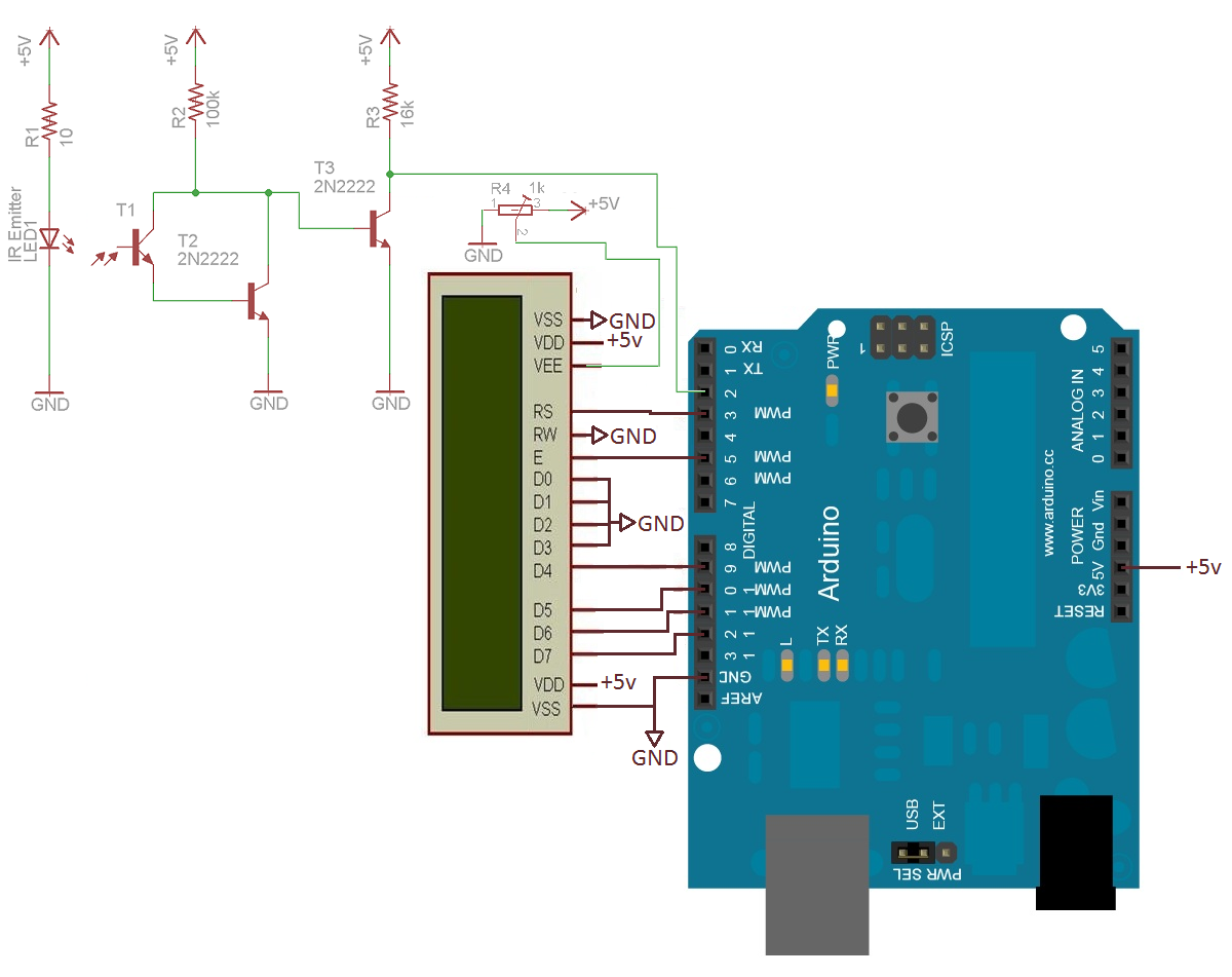
This article is about a contactless digital tachometer using arduino. Hopefully the pictures above wiring diagram can be useful. Tachometer circuit diagram using arduino use this diagram to make connections, if you are having trouble following this visual check the detailed explanation of the same below.
R2 change to 10k,, remove the c of t1 from c of t2, and c of t1 in series with a 10k resistor connecting to +5v. That is, as the motor rotates, the shaft cuts the internal light beam within the slot of the optocoupler (ic2). The ir sensor module consists of ir transmitter & receiver in a single pair that can work a digital tachometer for speed.
The ir module is digital sensor module which works on 5v supply voltage. Lets look at the required component and build it according to the circuit diagram below. The vcc is connected to the 5v pin of the arduino and the.
Emitter of the photo transistor is connected to the interrupt 0 (digital pin 2) of the arduino. The arduino interrupt is configured to be rising edge triggered. It differs from speedometer and odometer as these devices deal with linear or tangential velocity of the body while tachometer a.k.a.
Wheel of motor to whom rpm have to measure. R2 change to 10k, in series with a 2.2k resistor between the base of t3 and c of darlington. This article is about a contactless digital tachometer using arduino.
Connect the arduino with pc to upload code. Posted by unknown at 6:15 am. Here we learn how to build a simple ic 555 based tachometer circuit which can be used for directly measuring any frequency over an analogue volt meter.
//here we used fan which has 3 wings.
Arduino Tachometer Circuit
How to make Arduino based digital Tachometer or RPM

Arduino Blog » A simple Arduinobased tachometer
How to make a contactless digital tachometer using IR
Arduino Based Analog Speedometer Using IR Sensor
Arduino GPS Speedometer Circuit Diagram

Tutorial Arduino RevBurner driving a tachometer.
GitHub deepsyx/arduinotachometer Arduino car tachometer
Arduino Tachometer Hardware PyroElectro News
Distance Measurement Using Arduino and Ultrasonic Sensor

Simple Tachometer Circuit
Easy Peasy Tachometer Arduino Project Hub

Make this Simple Tachometer Circuit

Digital Tachometer using Arduino Microcontroller
Digital tachometer using arduino pdf

Simple Tachometer using IC 555

ADXL345 accelerometer interface with Arduino Circuit

Introduction to Digital Tachometer Circuit Working with
Arduino RPM Counter / Tachometer Code